In the injection molding process, clamping force (mold clamping force) is one of the key parameters determining mold stability, product quality, and equipment selection. Insufficient clamping force can lead to flash, dimensional instability, or even mold damage, while excessive clamping force increases costs. Therefore, knowing how to calculate clamping force in injection moulding is crucial for ensuring mold stability, product quality, and proper machine selection.
This article systematically introduces the definition of clamping force in injection molding, its influencing factors, and five commonly used calculation methods. It also provides engineering calculation examples to assist manufacturers and product engineers in selecting the most suitable clamping force and injection molding machine tonnage.
What is clamping force?
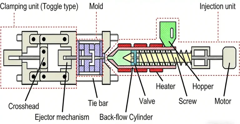
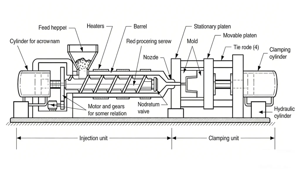
Clamping force, also known as mold clamping force, is the closing force applied by a hydraulic press to the mold during injection molding. It prevents the mold from being forced open by the high-pressure molten plastic during injection.
During injection molding, molten plastic is injected into the mold cavity at extremely high pressure. Insufficient clamping force can cause the mold parting line to open, resulting in flash, dimensional instability, or even mold damage.
Factors Affecting Mold Clamping Force
Selecting the appropriate clamping force impacts final product quality. Based on the mold clamping force formula: Clamping Force = Safety Factor × Injection Pressure × Projected Area, the following are key influencing factors.
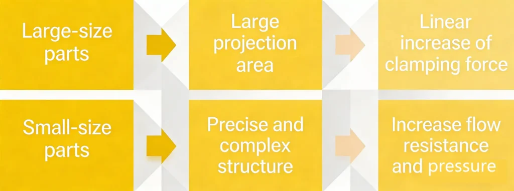
Part Geometry and Dimensional Complexity
The complexity of part geometry and dimensions directly affects the projected area and injection pressure, which are core variables in the clamping force formula.
Material Type and Flow Characteristics
Material is a key factor influencing injection pressure.
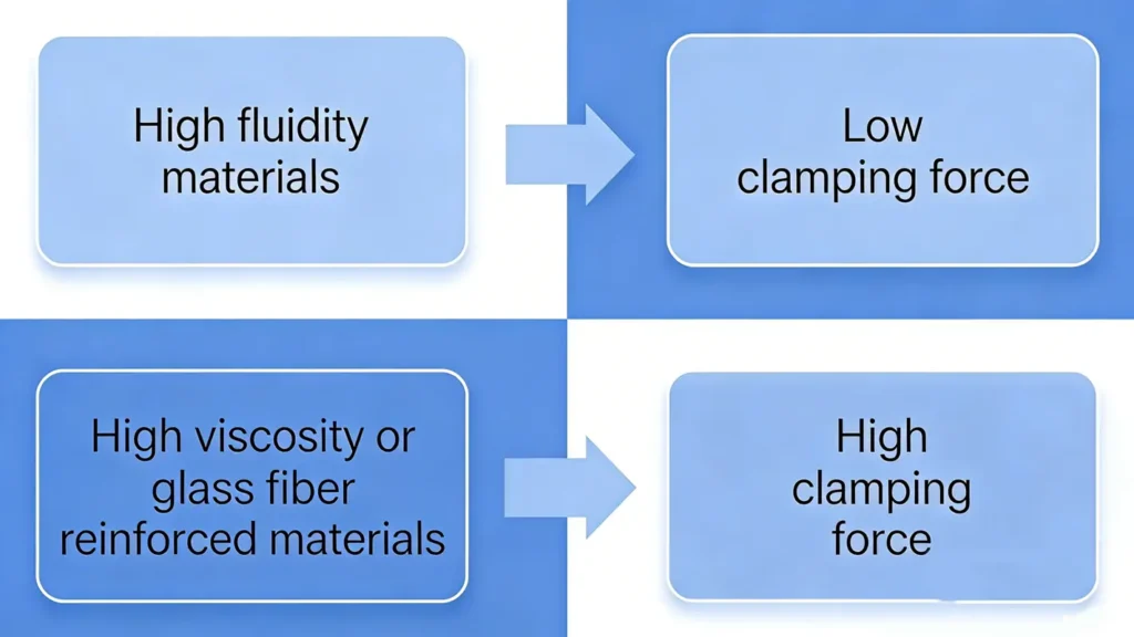
Among commonly used materials, HDPE typically requires low pressure, ABS requires medium pressure, while PC and PA require high pressure.
For more information on injection molding materials, please read: What Types of Plastic is Used in Injection Moulding?
Mold Structure and Cavity Count
Mold structure and cavity count directly impact projected area and pressure distribution. The use of multi-cavity molds, family molds, and hot runner systems is often one of the engineering reasons for doubling clamping force.
Wall Thickness
The wall thickness of a product affects flow resistance and holding pressure, thereby influencing injection pressure.
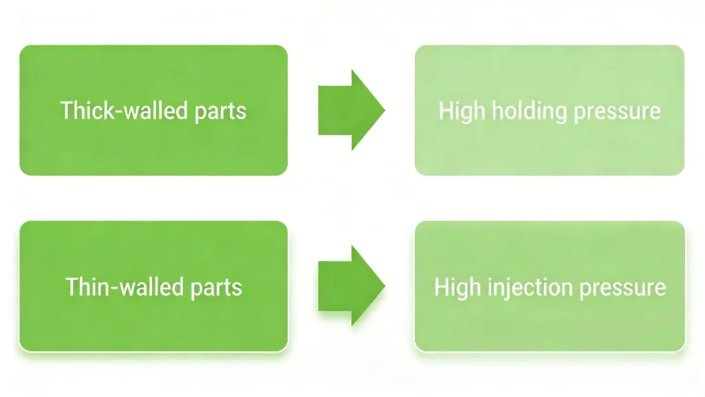
Both scenarios increase clamping force, but through different mechanisms.
Flow Length to Wall Thickness Ratio (L/T Ratio)
The flow length to wall thickness ratio determines pressure loss and flow resistance. A high L/T ratio leads to higher pressure, increasing clamping force. In actual production, thin-walled parts with long runners are most prone to issues, often resulting in extremely high clamping force.
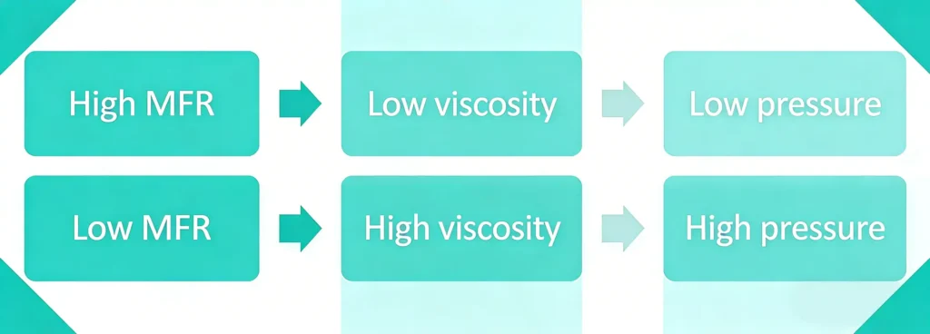
Melt Flow Rate
Melt flow rate serves as an engineering indicator of material viscosity, functioning as a quantitative parameter for material flowability.
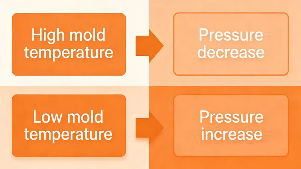
Mold Temperature
Mold temperature indirectly affects flowability and pressure, thereby indirectly influencing clamping force.
Safety Factor
Typically set at 1.1–1.5 to compensate for process fluctuations and equipment variations, the safety factor determines the final machine tonnage selection.
Why is it essential to calculate clamping force in injection molding?
Calculating clamping force is not merely a technical issue; it directly impacts costs and project risks.
Prevent flash and dimensional instability: Insufficient clamping force causes mold parting lines to open, resulting in flash, dimensional deviations, and cosmetic defects.
Avoid mold and equipment damage: Molds endure repeated high-pressure forces. Improper clamping force design may lead to mold damage or even equipment accidents.
Optimize injection molding machine tonnage selection:Over-specified machines increase capital investment and energy costs,while undersized machines compromise production stability.
Enhance production stability and yield:Precise clamping force calculations reduce trial mold runs, shorten project development cycles, and improve batch production consistency.
How to calculate clamping force in injection moulding?
Five common calculation methods suit different project phases and requirements:
Method 1: Standard Engineering Calculation Method
This is the most fundamental and commonly used calculation method in engineering.
Mold Clamping Force Formula
F = A × Pci × S
Common Conversion Formula
F (ton) = A (cm²) × Pci (kg/cm²) × S / 1000
Parameter Explanation:
| Symbol | Meaning | Common Units |
| F | Clamping Force | N / kN / ton |
| A | Projected Area | cm² / in² |
| Pci | Cavity Pressure | kg/cm² / MPa / psi |
| S | Safety Factor | 1.05 – 1.3 |
Recommended Safety Factor Selection
| Product Type | Recommended Safety Factor (S) | Description |
| General injection molded parts | 1.1 – 1.3 | Suitable for standard wall thickness and simple part structures |
| Thin-wall or high-precision parts | 1.3 – 1.5 | Thin walls have higher flow resistance and pressure fluctuations, requiring additional clamping force margin |
| High-risk or complex structural parts | > 1.5 | For multi-cavity molds, complex structures, reinforced materials, or projects with high quality risk requirements |
Calculation Example
Given Conditions:
Material: ABS
Projected Area A = 1250 cm²
Cavity Pressure Pci = 500 kg/cm²
Safety Factor S = 1.1
Calculation Process:
F = 1250 × 500 × 1.1 / 1000
F = 687.5 tons
The required injection molding machine tonnage must be rounded up to ≥ 700 tons.
Method 2: Empirical Coefficient Method
Mold Clamping Force Formula
F (ton) = A (cm²) × K
K = Empirical coefficient for clamping force per unit area
K Reference Table
| Product Type | K Value |
| General structural parts | 0.03 |
| Precision parts | 0.04 |
| Thin-wall parts | 0.05 |
| High-pressure materials | 0.06 |
Calculation Example
Given Conditions:
Projected Area = 200 in²
Material = ABS
Empirical Coefficient K = 3.5 ton/in²
Calculation Process
F = 200 × 3.5 = 700 tons
Recommended selection: 700–800 ton injection molding machine
Method 3: Material Empirical Pressure Method
Most commonly used for sales quotations and initial project evaluations.
Mold Clamping Force Formula
F = A × P(material) × S / 1000
Cavity Pressure Range Reference Table
| Material | Typical Cavity Pressure Range |
| PP (Polypropylene) | 200 – 400 kg/cm² |
| PE (Polyethylene) | 150 – 350 kg/cm² |
| ABS | 300 – 600 kg/cm² |
| PC (Polycarbonate) | 400 – 800 kg/cm² |
| PA (Nylon / Polyamide) | 500 – 1000 kg/cm² |
Calculation Example
Given Conditions:
Material: ABS
Empirical Cavity Pressure = 450 kg/cm²
Projected Area A = 800 cm²
Safety Factor S = 1.15
Calculation Process:
F = 800 × 450 × 1.15 / 1000
F = 414 tons
Method 4: Cavity Pressure Curve + Flow Coefficient Calculation
Mold Clamping Force Formula
Pci = Pci1 × F1
1 bar = 1.02 kg/cm²
F (ton) = A × Pci × 1.02 × S / 1000
Pci = Actual cavity pressure (bar)
Pci1 = Cavity pressure curve lookup value (bar)
F1 = Flow coefficient
Calculation Example
Given Conditions:
Material: ABS
Thickness t = 0.8 mm
Flow length L = 70 mm
Projected area A = 1250 cm²
Safety factor S = 1.1
Calculation Process
F:S = L / t = 70 / 0.8 = 87.5
Assume F:S = 100:1
Consulting the mold cavity pressure curve yields: Pci1 = 345 bar
Flow coefficient F1 = 1.35
Pci = 345 × 1.35 = 467.75 bar
Pci = 467.75 × 1.02 = 477.1 kg/cm²
F = 1250 × 477.1 × 1.1 / 1000
F = 655.8 tons
Method 5: CAE Simulation Method (Moldflow / Moldex3D)
Typically outputs directly from software: maximum cavity pressure, pressure distribution contour map, maximum clamping force, filling pressure curve. Suitable for precision calculations.
Accuracy and Application Comparison of Five Methods
| Method | Accuracy Level | Engineering Application |
| K-factor empirical method | Low | Rough estimation |
| Material-based empirical cavity pressure | Low | Cost quotation evaluation |
| Projected area × pressure method | High | Mold design |
| L/T ratio curve method | Medium | Engineering design |
| CAE simulation | High | Advanced engineering analysis |
Common Errors in Clamping Force Calculation
- Neglecting runner and gate area
- Failing to account for multiple cavities’ cumulative area
- Using theoretical pressure instead of actual process pressure
- Omitting safety factors
- Selecting injection molding machine tonnage based solely on product weight
Why Choose a Professional Injection Molding Engineering Team for Clamping Force Assessment?
Clamping force calculation is not merely a matter of formulas; it involves: mold design, material selection, process parameters, equipment selection, and cost evaluation. Understanding these factors requires extensive experience gained through real-world projects. Professional engineering teams can reduce trial mold runs, lower equipment investment risks, avoid common pitfalls, and ensure stable mass production.
If you want to learn how to choose an injection molding service provider, you can read: How to Find Plastic Injection Moulding Service:4 Success Factors and Top Plastic Injection Molding Services in 2026: A Comprehensive Guide to the Best Manufacturers and Solution
Conclusion
Mold clamping force significantly impacts product quality. Improper selection may cause flash, mold damage, or increased costs due to mismatched injection machine specifications. Understanding how to calculate clamping force for injection molds empowers you to select appropriate engineering designs.
If you have questions regarding the clamping force required for your project or injection molding machine specifications, our engineers can assist in calculating optimal tonnage and provide complimentary manufacturing consultation. Contact us today to optimize your injection molding process and reduce production costs.

Felix Lu
Senior DFM Expert · Huashuo Molding
Industry Exp.
Projects
DFM Optimization
Felix Lu has 16+ years of experience in mold manufacturing, DFM, and mass production, with a strong commitment to sharing advanced technologies and practical industry insights.