Introduction to Injection Molding Design
Injection molding design basics refers to the process of designing plastic parts to ensure they can be manufactured efficiently and consistently through the injection molding process. Good design encompasses not only the design of the plastic part itself but also its interaction with the mold during production, ensuring that the part is free of defects during injection, cooling, and ejection.
Factors such as wall thickness, draft angles, and material selection in plastic part design decisions determine the ease of molding and the stability of the production process… When designing parts with extremely reduced thickness, standard design rules shift significantly, making professional thin-wall plastic injection molding expertise crucial to prevent short shots and severe warpage.
This article provides a brief overview of injection molding design, aimed at helping you address these issues, mitigate risks, control costs, and improve overall production efficiency.
What Is an Injection Mold?
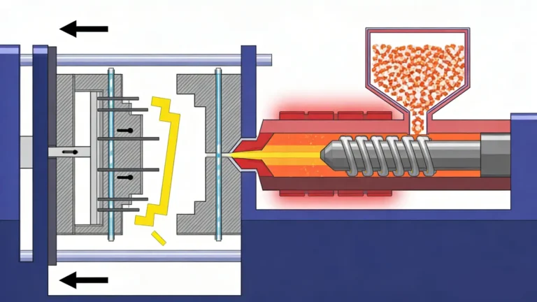
An injection mold is a tool used to shape molten plastic into finished parts. It consists of a core and a cavity; when these two parts are closed together, they form the precise shape of the product. During the manufacturing process, heated plastic is injected into this space, filling the cavity under pressure. It is then cooled and solidified, after which the mold opens and the part is removed.
The mold incorporates several key systems that control the part-forming process. The runner and gate systems are responsible for guiding the plastic into the cavity. The cooling system dissipates heat and controls the solidification process, which directly impacts the production cycle and part stability. The ejection system is responsible for removing the finished part from the mold without damage. These systems work together to ensure consistent results in every production cycle.
Injection molds are manufactured with high precision using materials such as tool steel or aluminum. They are designed to withstand high pressure and withstand repeated use while maintaining strict tolerances. A well-designed mold supports stable production, consistent quality, and efficient manufacturing, making it particularly suitable for high-volume part production in industries such as automotive, electronics, and consumer goods.
Basic Principles of Injection Mold Design
Injection mold design directly affects how a part is filled, cooled, and released during production. It starts from the part requirements, such as shape, tolerance, and surface quality, then translates them into a workable mold structure. A good design ensures stable production, consistent quality, and fewer defects.
Flow Balance and Filling Control
Flow balance controls how molten plastic moves through the runner and into the cavity. The goal is to fill all areas evenly and avoid defects like short shots or air traps. Gate position and runner layout play a key role in controlling the flow path. A balanced filling process improves part consistency and reduces molding defects.
Cooling System Design
Cooling design determines how heat is removed from the mold after injection. Cooling channels must be placed to keep temperature as even as possible across the mold. If cooling is uneven, parts may warp or shrink unevenly, and cycle time will increase. Material properties also affect cooling performance, so the system must be designed according to the plastic being used.
Shrinkage Compensation
Plastic materials shrink as they cool. The amount of shrinkage depends on the material type and processing conditions. Mold dimensions must be adjusted in advance to compensate for this change. If shrinkage is not considered, the final part may be smaller than required or out of tolerance.
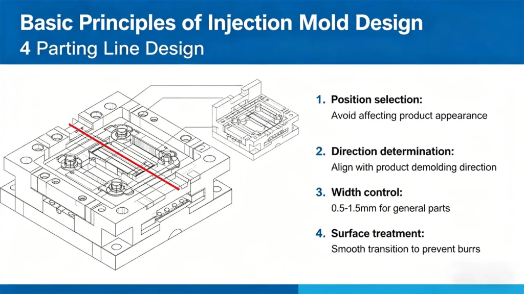
Parting Line Design
The parting line is where the two halves of the mold separate. Its position affects both appearance and manufacturability. A well-placed parting line avoids visible marks on key surfaces and reduces machining difficulty. It also needs to work with features like draft angles and undercuts to ensure smooth ejection and stable production.
Injection Mold Design Process
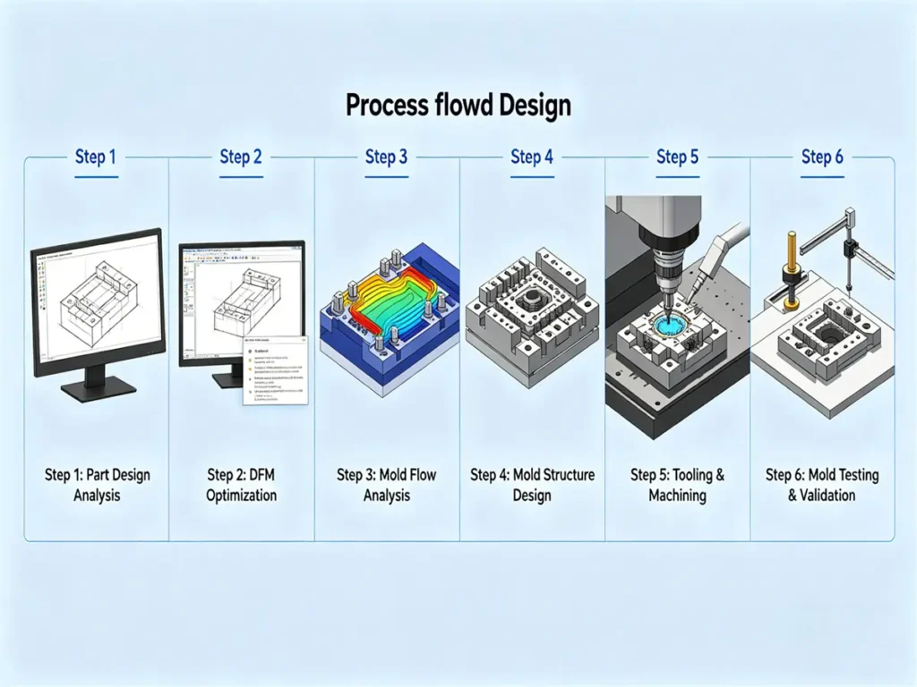
The injection mold design process is a structured workflow that starts from part requirements and ends with a validated production mold. Each step affects quality, cost, and stability in mass production. A complete process ensures the mold can produce consistent parts with minimal defects and efficient cycle time.
Step 1: Part Design Analysis
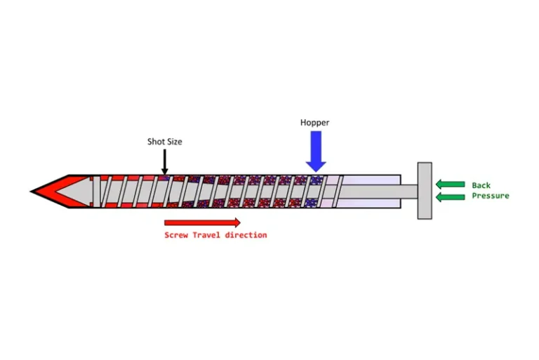
The process begins with a full review of the part requirements. This includes checking geometry, wall thickness, draft angles, tolerances, surface finish, and material properties. At the same time, the part must match the injection machine limits such as clamping force and shot size. The goal is to confirm the part can be molded without structural or processing issues.
Step 2: DFM Optimization
After the initial analysis, the design is optimized for manufacturing. This step focuses on improving moldability and reducing production risk. Features like undercuts, ribs, snap-fits, and wall transitions are adjusted to avoid complex tooling or unstable molding conditions. Proper DFM work helps reduce cost and prevents mold modifications later.
Step 3: Mold Flow Analysis
Mold flow simulation is used to predict how molten plastic will fill the cavity. It helps identify problems such as short shots, air traps, weld lines, shrinkage, and warpage before the mold is built. Based on the results, gate positions, flow paths, and cooling strategy are adjusted to improve filling balance and part quality.
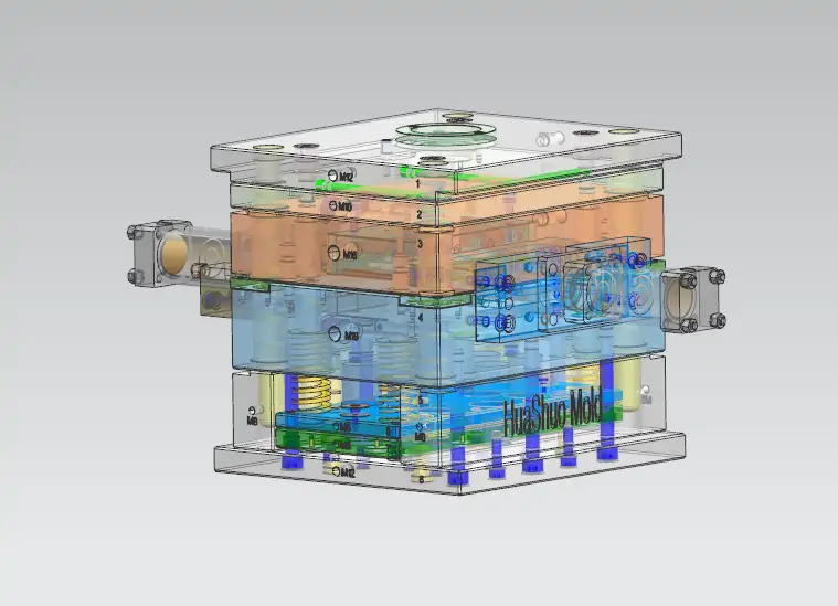
Step 4: Mold Structure Design
This step defines the full mold architecture, including cavity layout, core design, parting line, runner system, gate type, cooling channels, and ejection system. Cavity number is also determined based on production demand. Material shrinkage is applied during cavity sizing to ensure final part accuracy. A stable structure design ensures smooth molding and easy maintenance.
Step 5: Tooling & Machining
Once the design is finalized, mold components are manufactured using precision machining methods such as CNC milling, EDM, and grinding. High-quality tool steel or aluminum is used depending on production requirements. Critical areas such as cavities and cores are machined to tight tolerances to ensure accuracy and durability during long-term production.
Step 6: Mold Testing & Validation
After assembly, the mold goes through trial runs (T0, T1). Test shots are used to evaluate filling, cooling, part dimensions, and surface quality. Any issues such as shrinkage, flash, or warpage are corrected through mold adjustments. The process continues until the part meets all design and quality requirements.
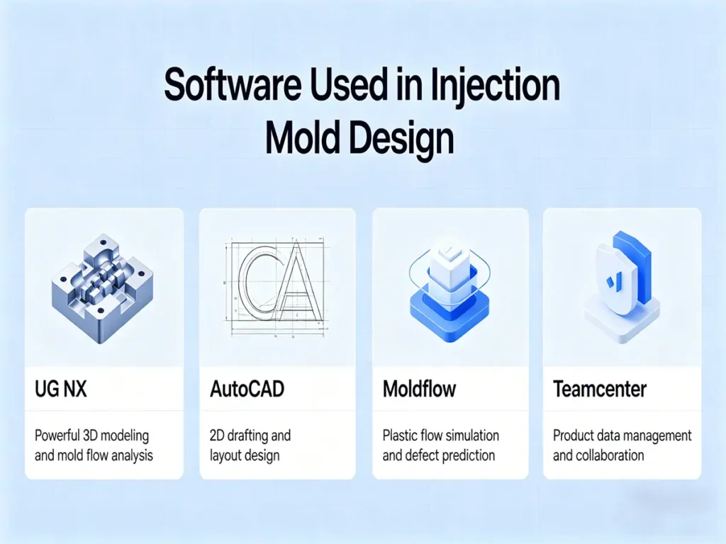
Software Used in Injection Mold Design
Injection mold design relies heavily on software tools across different stages, from concept design to simulation, manufacturing, and project coordination. Each type of software has a specific role, and together they form a complete digital workflow that improves accuracy, reduces risk, and shortens development time.
CAD Software
CAD software is the starting point of mold design. It is used to build precise 3D design models of mold structures, including cavities, cores, sliders, ejector systems, and cooling channels. It also allows designers to assemble components and check the overall structure before manufacturing begins.
In practice, tools such as SolidWorks, Autodesk Inventor, CATIA, and Siemens NX are commonly used, depending on project complexity and design requirements.
Mold Flow Analysis Software
Before a mold is built, mold flow simulation is used to study how molten plastic behaves inside the cavity. It helps identify potential defects such as air traps, weld lines, shrinkage, and warpage, which may affect part quality.
Based on these results, engineers can adjust gate locations, improve flow balance, and optimize cooling design. Moldflow, Moldex3D, and Simpoe are widely used in this stage for process prediction and optimization.
FEA (Finite Element Analysis) Software
FEA software focuses on the structural performance of the mold itself. It is used to analyze stress distribution, deformation, weak points, and fatigue under real injection conditions such as high pressure and temperature.
Common tools like ANSYS, Abaqus, and MSC Nastran help engineers improve mold strength and ensure long-term durability in production environments.
CAM Software
Once the design is finalized, CAM software is used to convert 3D models into machining instructions for CNC equipment. It defines tool paths for cutting, milling, and finishing operations, ensuring that mold components are manufactured with high precision.
Mastercam, PowerMill, and NX CAM are widely applied in mold manufacturing to improve machining efficiency and consistency.
Design Automation Software
Design automation software is used to reduce repetitive manual work in mold design. It helps standardize components, generate reusable templates, and build design libraries that speed up development and improve consistency across projects.
Tools such as Autodesk Configurator 360 and Tacton Design Automation are often used in standardized or high-volume mold design workflows.
Visualization and Collaboration Software
During the design process, collaboration tools are used to improve communication between engineers, designers, and manufacturers. They support real-time sharing, model review, annotation, and feedback, helping teams make faster and more accurate decisions.
Common platforms include Dassault 3DEXPERIENCE, Autodesk Fusion 360, and Siemens Teamcenter.
Material Selection for Injection Molding
Material selection is one of the key decisions in injection molding design. Different plastics have different strength, flow behavior, shrinkage, and surface finish, which directly affect how the part should be designed and manufactured.
Common Materials Comparison (ABS / PP / PC / Nylon)
| Material | Key Properties | Advantages | Limitations | Typical Applications |
| ABS | Balanced strength, toughness, good surface finish | Good appearance, easy to process, stable performance | Not UV resistant, moderate heat resistance | Consumer products, electronic housings |
| PP | Low density, good chemical resistance, flexible | Low cost, lightweight, good chemical resistance | High shrinkage, low stiffness | Packaging, automotive parts, containers |
| PC | High impact strength, transparent, heat resistant | Excellent toughness, optical clarity | Higher cost, stress cracking risk | Optical parts, safety covers, medical devices |
| Nylon (PA) | High strength, wear resistance, good fatigue performance | Strong mechanical properties, durable | Moisture absorption affects stability | Mechanical parts, gears, industrial components |
Each material presents a trade-off between cost, mechanical strength, and surface quality. Low-cost materials like PP are suitable for large-volume production where performance requirements are moderate. Materials like PC and Nylon are chosen when higher strength or durability is required, even at higher cost. ABS is often selected when a balance between appearance and performance is needed.
Material choice directly influences mold design parameters such as wall thickness, draft angle, cooling system, and shrinkage compensation. For example, materials with higher shrinkage require more precise cavity compensation, while materials with higher melting temperatures require better cooling efficiency. Moisture-sensitive materials like Nylon also require stricter process control during molding.
Common Injection Molding Defects and How Design Prevents Them
Injection molding defects are often not caused by processing alone, but by design issues in the early stage. A good part design can reduce or even eliminate many common defects before production starts.
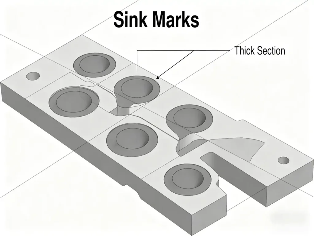
Sink Marks
Sink marks usually appear on thick sections of a part. They are caused by uneven wall thickness, where thicker areas cool slower and shrink more than surrounding regions.
Design solution:Keep wall thickness as uniform as possible and avoid sudden thickness changes. Use ribs instead of thick solid sections, and optimize cooling to improve heat removal in thicker areas.
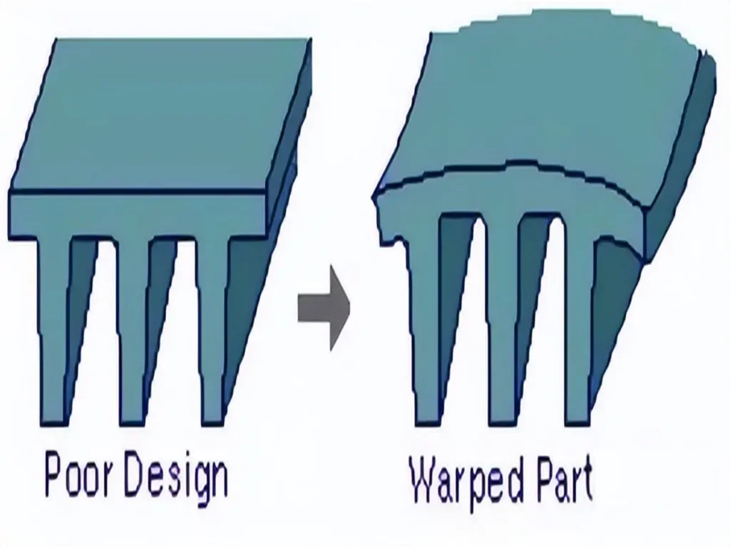
Warpage
Warpage is the deformation of a part after cooling. It is mainly caused by uneven cooling, inconsistent wall thickness, or unbalanced internal stress during molding.
Design solution:Design parts with balanced geometry and consistent wall thickness. Improve cooling system layout to ensure uniform temperature distribution, and use proper material selection to reduce shrinkage imbalance.
Weld Lines
Weld lines form when two flow fronts meet during filling. They are usually weak points and are caused by poor gate placement or complex flow paths.
Design solution:Adjust gate location to improve flow balance and reduce flow separation. Simplify part geometry where possible and ensure smooth material flow to avoid premature cooling before merging.
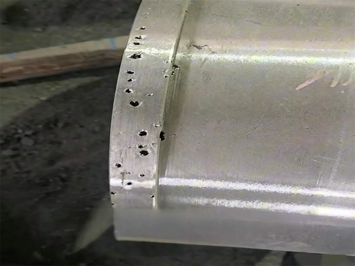
Air Traps
Air traps occur when air is unable to escape from the mold cavity during filling. This leads to incomplete filling or burn marks.
Design solution:Add proper venting areas and optimize flow paths to allow air to escape. Improve gate design and avoid enclosed regions where air can be trapped during injection.
Injection Molding Cost Optimization Tips
Injection molding cost is mainly determined by material usage, part design complexity, and mold structure. Small design improvements at an early stage can significantly reduce total production cost without affecting part quality.
Reduce Material Usage
Material cost is one of the biggest parts of injection molding expenses. Excessively thick walls or unnecessary solid sections increase both material consumption and cycle time.
Optimization approach:Use uniform wall thickness and reduce over-designed areas. Replace solid structures with ribs or hollow designs where possible, while still maintaining strength requirements.
Simplify Part Structure
Complex geometries increase tooling difficulty, machining time, and mold maintenance cost. Features such as deep undercuts, unnecessary curves, or overly tight tolerances can significantly raise production cost.
Optimization approach:Simplify geometry wherever possible. Avoid unnecessary undercuts and reduce the number of complex features. Design parts that are easier to mold, eject, and process.
Optimize Mold Design
Mold structure directly affects production efficiency and long-term cost. Poor cooling design, unbalanced flow, or complex multi-part assemblies can increase cycle time and maintenance cost.
Optimization approach:Design efficient cooling channels, balance flow paths, and simplify mold structure where possible. A well-optimized mold reduces cycle time and improves production stability.
Injection Molding Design Checklist
A good injection molding design should be checked against key rules before tooling starts. This helps reduce defects, improve manufacturability, and avoid costly mold changes later.
Maintain uniform wall thickness : Keep wall thickness consistent across the entire part to avoid sink marks, warpage, and uneven cooling.
Add proper draft angles : Include draft angles on vertical surfaces to ensure smooth part ejection and reduce mold wear.
Avoid sharp corners : Replace sharp edges with rounded corners to improve material flow and reduce stress concentration.
Optimize rib thickness : Design ribs at around 50–70% of wall thickness to strengthen the part without causing sink marks.
Select suitable materials : Choose materials based on strength, cost, appearance, and processing behavior to match product requirements.
Validate with mold flow analysi : Use simulation to check filling, cooling, and potential defects before building the mold.
Conclusion
Plastic injection molding defects are common in both development and mass production. Issues like sink marks, warpage, weld lines, and air traps usually result from combined factors in part design, material behavior, and processing conditions.
Effective defect control depends on optimizing three key areas: part design, mold structure, and process parameters. Uniform wall thickness, balanced flow paths, efficient cooling, and proper material selection are essential to achieving stable and high-quality results.
Huashuo Molding supports the full process, from design review and mold flow analysis to tooling optimization and production adjustment, helping reduce defects and improve consistency.
If you are facing injection molding defects, contact Huashuo for customized solutions and a free engineering evaluation.

Felix Lu
Senior DFM Expert · Huashuo Molding
Industry Exp.
Projects
DFM Optimization
Felix Lu has 16+ years of experience in mold manufacturing, DFM, and mass production, with a strong commitment to sharing advanced technologies and practical industry insights.